• Global CNC market projected to reach $128B by 2028 • New EU trade regulations for precision tooling components • Aerospace deman
NYSE: CNC +1.2%LME: STEEL -0.4%

Fixture Design Basics: How Clamping Layout Affects Accuracy and Cycle Time
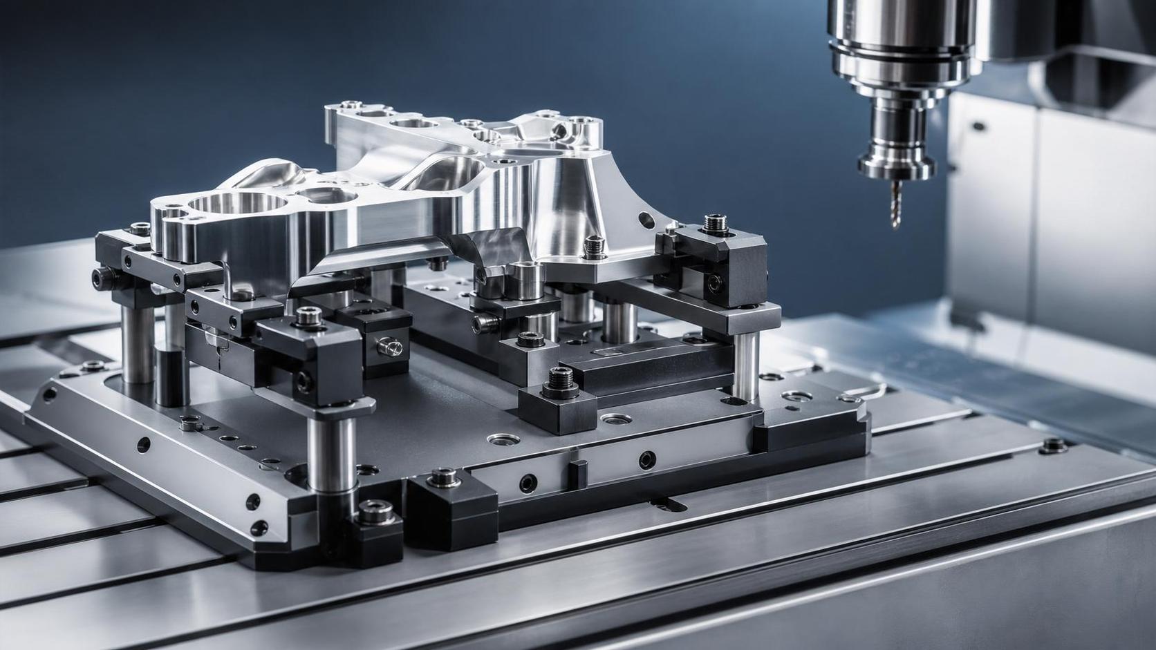
In CNC machining, Fixture Design is not a secondary setup detail. It shapes how a part reacts to cutting force, where variation enters the process, and how quickly each cycle can move from loading to finished machining.
That matters more now because machine tools are expected to deliver both precision and throughput across automotive, aerospace, energy equipment, and electronics production. As production systems become more automated and digitally connected, clamping layout has a direct effect on whether a process scales cleanly.
A well-planned fixture can improve repeatability, reduce scrap, and shorten non-cutting time. A poor one can force conservative cutting, create hidden distortion, and turn a capable machine into an unstable process.
Why clamping layout deserves closer attention
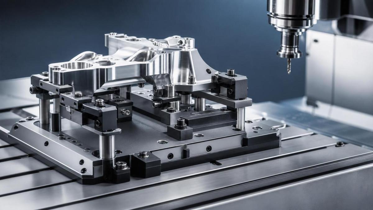
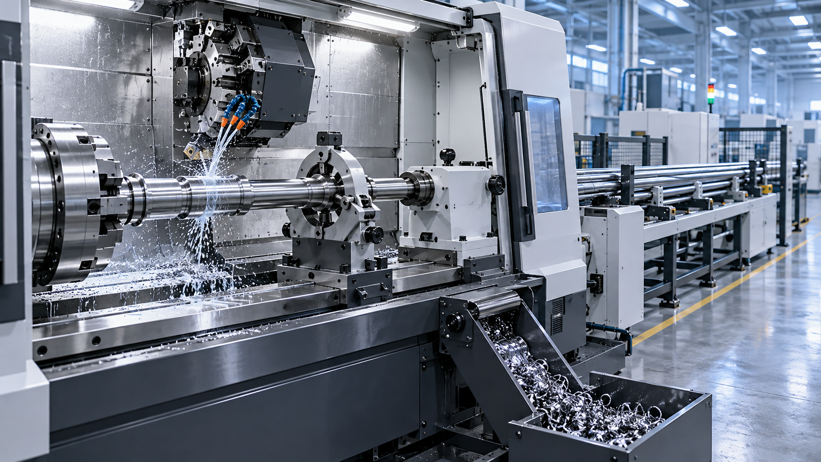
The image above relates to a common evaluation point: where clamps sit compared with datum surfaces, cutting zones, and thin-wall features.
Fixture Design defines how the workpiece is located, supported, and restrained. Clamping layout is the part of that design that determines where force is applied and how that force travels through the part.
In practice, accuracy problems often start here. Even a rigid machining center cannot correct a workpiece that is already bent, lifted, or unevenly stressed before the tool touches it.
Cycle time is also tied to layout. If clamps block tool paths, require manual repositioning, or slow loading, the fixture adds delay even when spindle time looks acceptable.
This is why Fixture Design is increasingly reviewed alongside spindle power, axis travel, probing, and automation compatibility. The fixture is part of the process capability, not just an accessory.
What a good fixture layout is really controlling
The basic goal is simple: hold the workpiece in a stable and repeatable condition while preserving access for cutting, inspection, and unloading. The difficulty comes from balancing several variables at once.
Support before force
Clamps should not be asked to do the job of supports. When support points are weak or poorly placed, clamping force pulls the part into shape temporarily, then releases stored stress after machining.
That is a common source of flatness loss, hole position error, and post-release dimensional drift.
Constraint without over-constraint
A fixture must locate all required degrees of freedom, but extra constraint can be just as damaging as insufficient restraint. Over-constraint often creates rocking, forced seating, or inconsistent contact on variable stock.
The familiar 3-2-1 locating logic still matters because it provides a disciplined way to separate location from clamping pressure.
Force path and cutting direction
Clamping layout works best when forces oppose expected cutting loads. If the tool pushes the part away from supports, chatter and dimensional movement become more likely.
On multi-axis equipment, this becomes more complex because the load direction changes with tool orientation. Fixture Design must then consider the full machining sequence, not a single operation view.
Where accuracy is usually gained or lost
Several recurring issues explain why two processes using similar machines can produce very different results.
- Thin sections are clamped near unsupported spans, causing elastic deformation during machining.
- Datum selection does not match the final functional geometry, so location is stable but not relevant.
- Clamp points are too close to machining zones, allowing vibration transfer and local distortion.
- Workholding surfaces collect chips or coolant residue, reducing seating repeatability.
- Hydraulic or pneumatic clamping varies because pressure control is not matched to part stiffness.
In high-precision sectors, these are not small setup details. They influence Cpk, rework rates, and the reliability of in-process measurement.
This is especially relevant in global machine tool supply chains, where comparable parts may be produced across different plants, fixture suppliers, and automation cells.
How clamping layout changes cycle time
Fixture Design affects cycle time in two ways. One is direct, through loading, unclamping, indexing, and tool access. The other is indirect, through the cutting parameters the setup can safely support.
If the part is held rigidly, feed rates can increase and finishing passes may be reduced. If the setup is marginal, process planners usually compensate with lighter cuts, extra operations, or manual checks.
Usually, the biggest time savings come from eliminating avoidable reclamping. Every additional setup adds handling, introduces new datum transfer risk, and complicates automation.
Different parts demand different Fixture Design priorities
Not every clamping strategy should aim for maximum force or maximum simplicity. Part geometry and production mode change what matters most.
Prismatic structural parts
These often benefit from clear datum faces and modular clamping. The key issue is keeping enough access for multiple faces without sacrificing rigidity.
Thin-wall housings and covers
Here, Fixture Design should focus on distributed support, controlled clamp force, and careful load paths. Vacuum or low-force systems may be justified when mechanical clamps distort the part.
Shafts and rotational components
Concentricity, axial location, and dynamic balance matter more. Soft jaws, collets, centers, or custom nests are chosen based on whether speed, runout control, or surface protection is the priority.
High-mix production
Flexible fixtures, modular elements, and shorter changeover often outweigh the benefits of a highly specialized design. In this setting, repeatable setup logic is as important as ultimate rigidity.
What to check when comparing production solutions
A useful evaluation goes beyond asking whether the fixture holds the part. The better question is whether the layout supports the intended process window over time.
- Does the locating scheme reference functional datums or just convenient stock surfaces?
- Can clamp force be adjusted according to material, wall thickness, and operation stage?
- Is there enough clearance for tools, probes, chip evacuation, and coolant flow?
- Will the fixture support robotic loading or palletized changeover without extra intervention?
- What happens to accuracy after thermal growth, wear, or repeated maintenance cycles?
- Can the process maintain consistency across plants, suppliers, or shifts?
These checks are increasingly important as machining cells become part of broader smart factory systems. Digital integration only works well when the physical process is stable enough to trust.
Practical steps for stronger fixture decisions
Fixture Design improves fastest when it is reviewed with the machining process, not after the toolpath is already fixed.
Start by mapping the functional dimensions of the part. Then align locating features and clamp points with those dimensions, the expected cutting force, and the most deformation-sensitive areas.
Next, test the sequence. A layout that looks rigid in a static model may fail when roughing removes support mass before finishing operations begin.
Where tolerance is tight, use measurement data to compare part condition in three states: free, clamped, and post-machining release. That reveals whether fixture force is solving a problem or creating one.
It is also worth reviewing maintainability. Replaceable contact elements, accessible cleaning points, and clear pressure settings help preserve the original Fixture Design intent over long production runs.
For the next evaluation step, build a short checklist around datum logic, force path, access, automation fit, and measured repeatability. That framework makes solution comparison more reliable than judging fixture complexity by appearance alone.
Recommended for You
 Digital Manufacturing for Smart Factories: Connecting Legacy Machines to MESMachine Tool Industry Editorial Team
 How to Select a CNC Metal Lathe for Tight-Tolerance Shaft and Sleeve PartsCNC Machining Technology Center
 How to Select an Industrial Lathe for High-Volume Shaft ProductionMachine Tool Industry Editorial Team
 Selecting Machine Tools for Automotive Parts: Accuracy, Throughput, and AutomationMachine Tool Industry Editorial Team
 Industrial Machining: Selecting Processes for Tight-Tolerance Metal PartsCNC Machining Technology Center
 Manufacturing Technology Trends That Improve Throughput and Quality ControlManufacturing Market Research Center

Aris Katos
Future of Carbide Coatings
15+ years in precision manufacturing systems. Specialized in high-speed milling and aerospace grade alloy processing.
▶
How to Design Cost-Effective Fixtures That Maintain Cycle Time in Mass ProductionCNC Machining Technology Center▶
Zero-Point Clamping or Modular Fixtures? Choosing a Faster CNC Changeover SystemCNC Machining Technology Center▶
How to Cut CNC Fixture Changeover Time Without Sacrificing Part AccuracyCNC Machining Technology Center▶
Can One Fixture Handle Multiple Part Geometries Efficiently?CNC Machining Technology Center▶
Fixture Design Cost Breakdown: What Buyers Should Review Before RFQ and ApprovalCNC Machining Technology Center
Mastering 5-Axis Workholding Strategies
Join our technical panel on Nov 15th to learn about reducing vibrations in thin-wall components.

Providing you with integrated sanding solutions
Before-sales and after-sales services
Comprehensive technical support