• Global CNC market projected to reach $128B by 2028 • New EU trade regulations for precision tooling components • Aerospace deman
NYSE: CNC +1.2%LME: STEEL -0.4%

Selecting Machine Tools for Automotive Parts: Accuracy, Throughput, and Automation
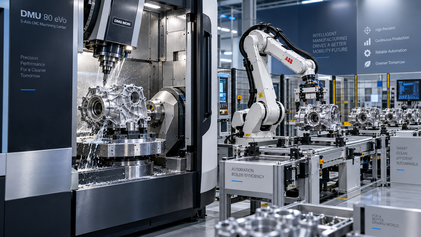
For automotive parts, the best machine tool is rarely the one with the highest headline accuracy or the shortest demonstrated cycle time. It is the machine that can hold the required capability over long production runs, recover predictably after tool changes or interruptions, and fit the intended level of automation without creating a bottleneck elsewhere in the cell.
That distinction matters because automotive machining combines demanding tolerances with volume pressure. A spindle, housing, shaft, brake component, transmission part, or EV structural casting may be within tolerance on the first few pieces yet become expensive if thermal drift, clamping variation, chip control, or loading time erodes consistency across a shift. Technical evaluation should therefore begin with the part family and production system, not with a generic comparison of machine specifications.
Start with the process window, not the brochure specification
A machine tool for automotive industry applications should be assessed against the process window required by the finished part. This includes dimensional tolerance, geometric tolerance, surface finish, material behavior, feature accessibility, and the allowable variation over the intended production period.
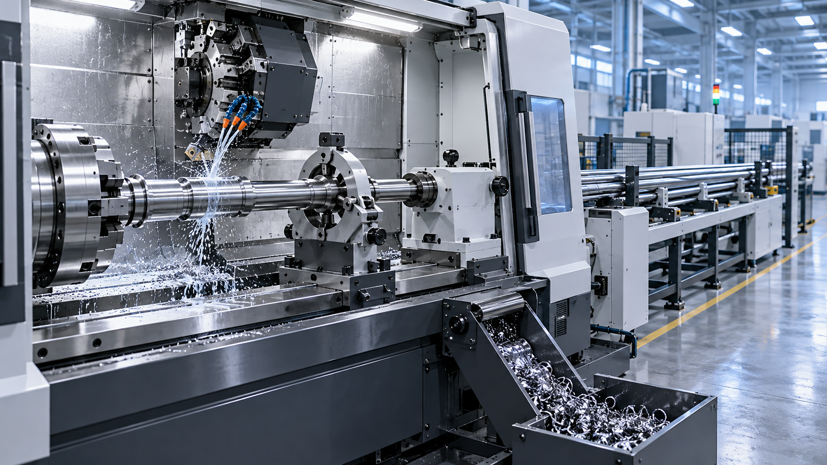
For example, a turning center for a precision shaft may need stable control of diameter, runout, concentricity, and shoulder location across multiple operations. A machining center for an aluminum EV housing may be judged more heavily on rigidity during high-material-removal roughing, chip evacuation, tool-life management, and the repeatability of deep or interrupted features. These are different evaluation problems even when both machines advertise similar positioning accuracy.
Static positioning figures remain useful, but they do not describe the full production condition. Evaluators should ask how the machine behaves under the actual cutting load, with the expected fixture, tool extension, coolant method, and material batch variation. A high-accuracy platform can still produce unstable results if the process depends on a weak workholding arrangement or a long, vibration-prone tool assembly.
- Define the critical-to-quality features before comparing machine configurations.
- Separate tolerance requirements for roughing, semi-finishing, and finishing operations.
- Review thermal behavior over an operating cycle rather than only after a short warm-up.
- Assess spindle, axis, and structure performance under the anticipated cutting forces.
- Include fixture repeatability and part datum strategy in the machine evaluation.
For high-volume components, process capability is often more valuable than achieving an exceptional result on a single trial part. The preferred machine is one that leaves sufficient margin between normal process variation and the drawing limits.
Cycle time must include the work around the cut
Cycle-time discussions often focus on rapid traverse rates, spindle speed, acceleration, or tool-change time. Those values matter, but they can lead to a misleading selection when they are considered in isolation. The relevant measure is the completed-part cycle: loading, clamping, probing, machining, chip clearing, unloading, inspection interaction, and any recovery time caused by alarms or manual intervention.
In automotive production, a few seconds lost outside the cutting cycle can outweigh a modest improvement in metal-removal time. A machine with a fast spindle but awkward loading access may be less productive than a slightly slower alternative designed for robotic tending. Similarly, a multi-axis machine can consolidate setups and reduce handling, but it may not be the most economical answer for a stable, high-volume part with simple geometry. Multiple dedicated machines can sometimes offer better throughput, easier maintenance planning, and less exposure to a single point of failure.
The right comparison is therefore between production concepts, not merely between individual machines. A technical team should model the line around expected output, including planned tool changes, inspection frequency, part transfers, and realistic equipment availability. This avoids selecting a machine that meets the nominal takt time only under ideal conditions.
Automation compatibility is a process design question
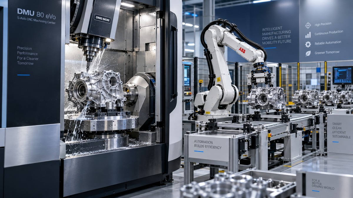
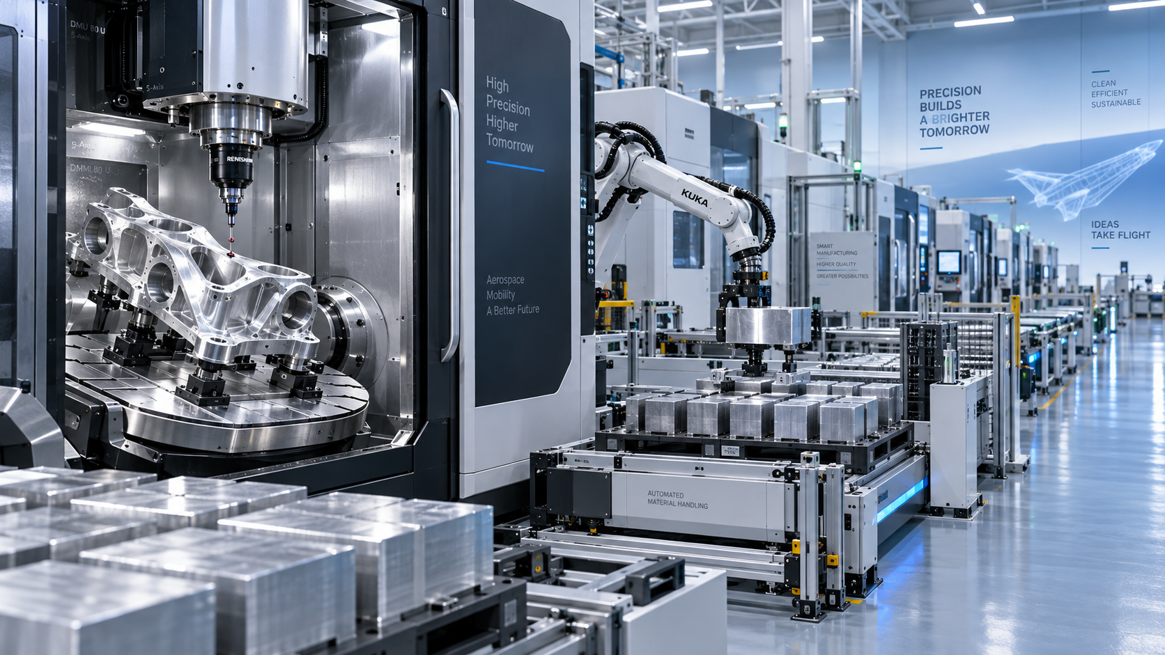
Automation is often treated as an add-on: select the CNC machine first, then attach a robot, gantry, pallet system, or conveyor. That approach can produce avoidable integration problems. Automation changes how the machine must be specified, from door geometry and chuck access to fixture location, signal interfaces, chip handling, coolant management, and error recovery.
For a simple rotational component, bar feeding or automated chuck loading may be sufficient. For cast or forged parts, the cell may require orientation control, de-burring allowances, part-presence sensing, washing, marking, and in-process gauging. A machine that is technically capable of cutting the component may still be a poor automation choice if the loading sequence is difficult to standardize.
Technical evaluators should examine the machine as part of a cell and test the following questions early:
- Can the automation system load and unload parts without interfering with tools, fixtures, or chip flow?
- Does the machine provide reliable interfaces for interlocks, status signals, traceability, and quality data?
- Can operators access the work zone safely for tool setting, recovery, and maintenance?
- Will chip type and coolant carryover disrupt grippers, sensors, pallets, or downstream inspection?
- Can the cell recover from a stopped machine or rejected part without extensive manual intervention?
For mixed production, flexibility deserves particular scrutiny. A pallet pool or robotic cell can improve machine utilization, yet frequent fixture changes, tool management complexity, or lengthy requalification can offset the expected benefit. The level of automation should match part-family stability and demand predictability, rather than serving as a proxy for manufacturing sophistication.
Choose configuration by part behavior
Machine configuration should follow the physical behavior of the component during machining. Thin-wall housings, long shafts, hard steel gears, aluminum castings, and large chassis parts place very different demands on the machine.
Multi-axis capability should be justified by setup reduction, feature access, or accuracy improvement. It is particularly valuable where multiple datums and repeated reclamping would accumulate error. But extra axes also add programming demands, collision risk, maintenance requirements, and potential constraints on automation access. A simpler horizontal or vertical machining center may provide a more controllable production route when the part geometry allows it.
Evaluate accuracy as a system, not a machine attribute
Automotive quality requirements are determined by the combined behavior of the machine, toolholder, cutting tool, fixture, measurement method, material, program, and operator or automation logic. Machine geometry is foundational, but it cannot compensate for an unstable process chain.
A practical assessment should connect each critical feature to its error sources. Bore position may be affected by thermal growth, fixture seating, probe repeatability, tool deflection, and tool wear. A turned diameter may depend on spindle condition, cutting-edge wear, material hardness variation, coolant temperature, and compensation discipline. Once those sources are visible, the evaluation team can decide whether the solution needs probing, in-process gauging, closed-loop compensation, more rigid fixturing, or a different operation sequence.
This also changes how acceptance trials should be structured. Demonstration parts should reflect the real material condition and feature mix as closely as possible. Trials based only on an easy sample part may confirm machine motion but say little about the risk of production drift.
Look beyond acquisition price
The lowest purchase price can be costly if it produces frequent adjustments, unstable tool life, excessive floor intervention, or difficult service access. At the same time, the most advanced machine can be an inefficient investment when its capability is largely unused.
The decision should compare total manufacturing impact: labor content, tooling consumption, fixture complexity, energy and coolant handling, maintenance access, spare-parts exposure, programming effort, inspection burden, and downtime consequences. In a tightly balanced automotive line, maintainability can be as important as nominal performance. A machine that permits rapid tool replacement, straightforward diagnosis, and repeatable restart procedures protects output when disturbances occur.
A sound selection process ends with a defined manufacturing scenario: the target part family, required volume range, critical features, automation boundary, inspection strategy, and likely sources of variation. Once those conditions are explicit, accuracy, throughput, and automation can be evaluated as connected requirements rather than competing checklist items.
Recommended for You
 Digital Manufacturing for Smart Factories: Connecting Legacy Machines to MESMachine Tool Industry Editorial Team
 How to Select a CNC Metal Lathe for Tight-Tolerance Shaft and Sleeve PartsCNC Machining Technology Center
 How to Select an Industrial Lathe for High-Volume Shaft ProductionMachine Tool Industry Editorial Team
 Selecting Machine Tools for Automotive Parts: Accuracy, Throughput, and AutomationMachine Tool Industry Editorial Team
 Industrial Machining: Selecting Processes for Tight-Tolerance Metal PartsCNC Machining Technology Center
 Manufacturing Technology Trends That Improve Throughput and Quality ControlManufacturing Market Research Center

Aris Katos
Future of Carbide Coatings
15+ years in precision manufacturing systems. Specialized in high-speed milling and aerospace grade alloy processing.
▶
Digital Manufacturing for Smart Factories: Connecting Legacy Machines to MESMachine Tool Industry Editorial Team▶
Selecting Machine Tools for Automotive Parts: Accuracy, Throughput, and AutomationMachine Tool Industry Editorial Team▶
Smart Manufacturing for Small Businesses: Where Automation Delivers the Fastest ROIMachine Tool Industry Editorial Team▶
How Smart Manufacturing Technology Improves OEE Across Industry 4.0 Production LinesMachine Tool Industry Editorial Team▶
How to Evaluate an Automation Line for Electronics Production Before InvestmentMachine Tool Industry Editorial Team
Mastering 5-Axis Workholding Strategies
Join our technical panel on Nov 15th to learn about reducing vibrations in thin-wall components.

Providing you with integrated sanding solutions
Before-sales and after-sales services
Comprehensive technical support