• Global CNC market projected to reach $128B by 2028 • New EU trade regulations for precision tooling components • Aerospace deman
NYSE: CNC +1.2%LME: STEEL -0.4%

How thermal drift affects accuracy in high-precision manufacturing
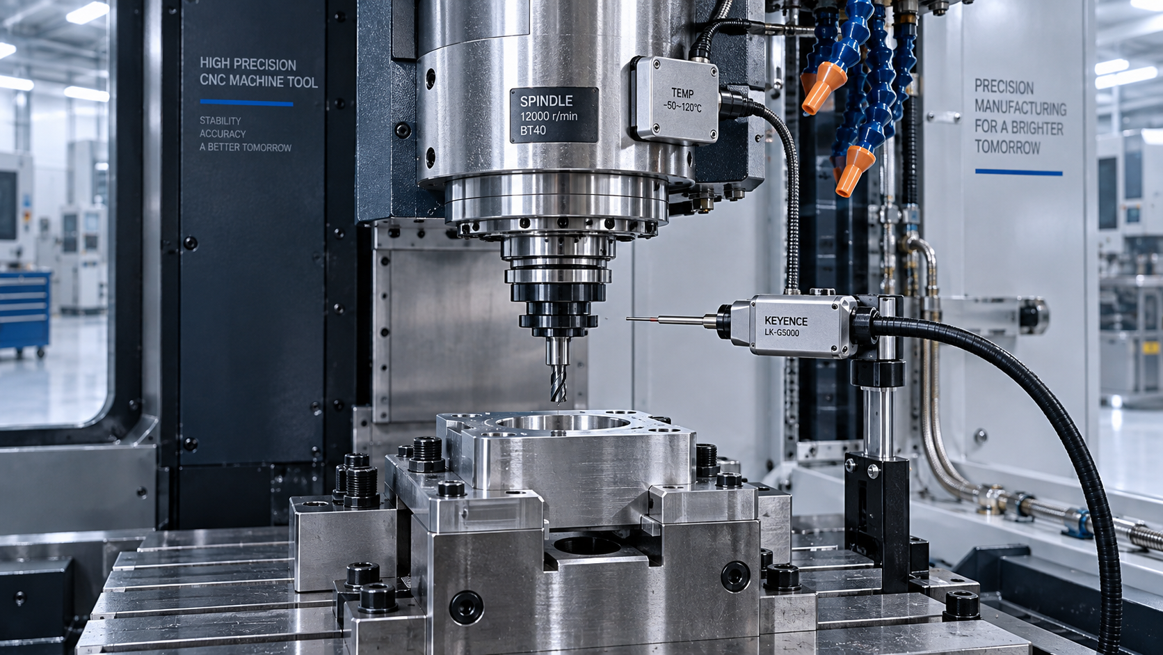
Thermal drift changes the position of a cutting edge relative to the workpiece as a CNC machine heats, cools, or develops temperature gradients. A machine that passes an initial accuracy check can therefore produce different dimensions later in the same shift. In high-precision manufacturing, accuracy must be evaluated across the operating temperature cycle, including startup, sustained cutting, interruptions, and restart. A geometric accuracy result obtained under one thermal condition does not establish dimensional stability under every production condition.
The acceptance question is whether temperature-related movement, workpiece expansion, and measurement uncertainty remain within the available tolerance budget. Answering it requires separating these effects: a tool position error changes the cut, a warm workpiece changes size, and an unstable inspection system changes the reported result.
The error develops along the tool-to-workpiece path
Heat enters a machine through spindle bearings, motors, axis drives, cutting, and surrounding equipment. These sources warm different structures at different rates. The resulting expansion shifts the spindle nose, moves axis components, and changes the relationship between the table and tool. The dimensional consequence follows the complete structural path connecting the cutting edge to the workpiece datum.
For a freely expanding component at a reasonably uniform temperature, length change can be estimated using ΔL = α × L × ΔT, where α is the material’s coefficient of thermal expansion, L is the original length, and ΔT is the temperature change. This relationship explains why long structural paths deserve attention. It does not predict the complete machine error: real assemblies have constraints, mixed materials, joints, and uneven temperature distributions.
Uniform growth and thermal bending also produce different machining signatures. Axial spindle growth can shift tool length and pocket depth. A temperature difference across a column can tilt the spindle, creating position-dependent errors across the table. On a turning center, movement between the spindle axis and tool tip affects diameter; movement along the spindle axis affects shoulder locations. One offset correction cannot necessarily address both effects.
Position feedback determines which changes the controller can observe. A motor encoder does not directly measure ball screw thermal growth. A linear scale measures axis position more directly, but expansion elsewhere in the structure still changes the cutting relationship. The scale itself also has thermal behavior. Closed-loop positioning therefore does not automatically remove thermal error at the tool tip.
Temperature readings need a time history
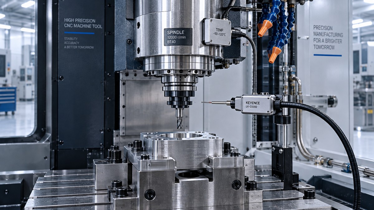
A stable room temperature is useful, but it does not establish a stable machine. Internal heat generation can continue while the ambient temperature remains unchanged. Conversely, a room temperature change can reach the enclosure, bed, spindle, and workpiece at different times. Two production runs with the same current temperature reading can have different errors because their preceding thermal histories differ.
Spindle duty is particularly important. A warm-up performed at one speed does not necessarily reproduce the bearing and motor temperatures generated by the production program. Intermittent acceleration, tool changes, and idle periods alter heat input. Axis travel matters too: a short repeated stroke heats the drive system differently from movement across the full working envelope.
Coolant links the machine’s thermal condition to the workpiece. Its temperature affects cutting-zone heat removal and the temperature of structures it contacts. A coolant reservoir that progressively warms can introduce drift even when the room is controlled. Sensor placement must reflect this mechanism; a reading from a remote reservoir location may not represent coolant entering the cutting zone.
Warm-up should therefore be defined by observable stability under representative conditions. A fixed elapsed time is useful only after validation shows that it consistently brings the relevant errors within an acceptable range. Long stoppages, unusual spindle loads, or changes in coolant operation can invalidate that assumption.
Distinguishing machine drift from a warm part
A measured size change does not, by itself, identify the source. A component measured immediately after machining can be larger than it will be after cooling. If the measured surface is still developing a temperature gradient, simple expansion correction can be misleading. Thin walls, thick bosses, and internal pockets equilibrate at different rates, so the part can change shape as well as overall size.
Workholding adds another constraint. A warm component clamped against a fixture cannot always expand freely. Clamping forces, contact friction, and material differences redistribute movement. After release and temperature equalization, the measured geometry can differ from the geometry present during cutting. This is especially relevant when finishing occurs while the part remains hot from roughing.
The following observations provide starting points for diagnosis, rather than proof of a single cause:
Tool wear and thermal drift can occur together. Wear often follows accumulated cutting exposure, while thermal displacement follows heating and cooling with a time lag. Comparing continuous cutting, idle running, and cooldown data helps separate them. Changing offsets after every observed dimensional shift can conceal the cause and create a reverse error when the machine cools.
Inspection must preserve the reference condition
Dimensional specifications relate to a defined reference condition. The drawing, inspection procedure, and applicable standard should establish how temperature is handled. A machine accuracy test and a finished-part acceptance measurement serve different purposes: the first characterizes equipment behavior under stated conditions; the second determines whether the component meets its specified requirements.
Temperature correction requires a suitable expansion coefficient, a representative temperature measurement, and a sufficiently uniform thermal state. Using a nominal material coefficient without considering alloy variation or measurement uncertainty can overstate confidence. For assemblies containing different materials, applying one correction to the entire structure can distort the result.
Inspection equipment also changes with temperature. A coordinate measuring machine, reference artifact, gauge, and workpiece need compatible thermal conditions. Equilibration should be based on evidence appropriate to part geometry and tolerance, rather than a universal waiting period. Surface temperature alone does not establish that a thick section has reached the same temperature internally.
On-machine probing provides useful feedback, but it shares part of the machine’s structural error path. If the cutting operation and probing cycle experience correlated movement, the probe can report apparent consistency while an independent measurement reveals a shifted feature. Agreement between cutting and probing is therefore weaker evidence than agreement with a suitably controlled external reference.
Characterizing drift under production conditions
A useful thermal study records displacement and temperature against time while preserving the operating sequence. Relevant records include spindle speed and load, axis motion, coolant condition, ambient temperature, interruptions, and the timing of each measurement. Measurements taken only at startup and shutdown can miss intermediate peaks or a reversal in error direction.
For machine-level evaluation, displacement measurements should represent the tool-to-workpiece relationship and the directions relevant to the part. A single sensor near the spindle cannot fully describe angular changes or errors across a large work envelope. Reference artifacts and measurement fixtures must also have characterized thermal behavior; otherwise their expansion becomes part of the apparent machine drift.
A practical validation sequence can include:
- Establish a repeatable starting condition and record the initial error using a defined reference setup.
- Run a cycle that represents production spindle duty, axis travel, coolant use, and idle periods. Capture the transient behavior as well as the eventual steady condition.
- Introduce a representative interruption, then observe restart. This reveals whether the original warm-up rule and compensation remain valid after partial cooling.
- Repeat the sequence on separate occasions to assess whether the relationship between temperature and error is reproducible.
When a formal thermal-effects test is required, the applicable machine-tool test procedure should govern the setup, reporting, and environmental conditions. Results need their operating context: compensation state, sensor locations, machine configuration, and measurement uncertainty. A low drift value without those details is difficult to apply to a different part or production cycle.
Choosing control measures that match the mechanism
Reducing the heat disturbance is often the most predictable intervention. Stable coolant delivery, suitable spindle cooling, controlled airflow, and separation from direct sunlight or nearby heat sources reduce changing thermal loads. Maintenance matters because deteriorating bearings, restricted cooling circuits, and altered lubrication can change the heat pattern on which an established process relies.
Process scheduling can also reduce dimensional variation. Keeping finishing operations within a validated thermal window limits the difference between early and late parts. Where roughing generates substantial workpiece heat, a controlled pause or separate finishing stage allows the part to approach a suitable temperature. The required sequence depends on geometry, material, stock removal, and tolerance.
Thermal compensation adjusts commanded positions using measured temperatures, operating history, or an estimated thermal state. Its effectiveness depends on whether the model represents the machine’s actual behavior. A model established with one spindle duty or axis pattern should be validated before use under substantially different conditions. Sensor delay, failed sensors, and changes after maintenance require explicit handling.
A scalar tool-length correction is suitable only when the dominant error behaves like displacement along that direction. It cannot fully correct a tilted spindle or position-dependent distortion. Likewise, part-based offset updates combine several influences unless tool wear, workpiece temperature, and measurement uncertainty are separately controlled.
Making thermal limits part of dimensional acceptance
The thermal allowance should fit within the complete uncertainty and error budget. Geometric error, tool deflection, fixture variation, workpiece temperature, and inspection uncertainty all compete with thermal drift for the available tolerance. Allocating the entire tolerance to observed machine movement leaves no margin for these other contributions. Combining them also requires attention to correlation; a simple root-sum-square calculation is inappropriate when independence has not been established.
Production limits should connect observable conditions to demonstrated dimensional capability. These can include a validated range of coolant temperature, a displacement stability criterion, or a defined recovery condition after a stoppage. Temperature alone is an adequate release indicator only when testing has established its relationship to the relevant dimensional error.
If the process leaves its validated thermal range, affected production should remain traceable to the last demonstrated acceptable condition. Records linking parts to cycle times, interruptions, temperature trends, compensation changes, and inspection results make the boundary reviewable. For features governing interference fits, sealing, or alignment, acceptance must reflect the specified final condition rather than a favorable measurement taken while the component is still warm.
NEXT ARTICLE
Recommended for You
 How to Cut CNC Machining Energy Use per Part Without Longer Cycle TimesCNC Machining Technology Center
 How thermal drift affects accuracy in high-precision manufacturingCNC Machining Technology Center
 How to verify spare part compatibility for Yunnan CY Group lathesMachine Tool Industry Editorial Team
 Digital Manufacturing for Smart Factories: Connecting Legacy Machines to MESMachine Tool Industry Editorial Team
 How to Select a CNC Metal Lathe for Tight-Tolerance Shaft and Sleeve PartsCNC Machining Technology Center
 How to Select an Industrial Lathe for High-Volume Shaft ProductionMachine Tool Industry Editorial Team

Aris Katos
Future of Carbide Coatings
15+ years in precision manufacturing systems. Specialized in high-speed milling and aerospace grade alloy processing.
▶
How thermal drift affects accuracy in high-precision manufacturingCNC Machining Technology Center▶
Industrial Machining: Selecting Processes for Tight-Tolerance Metal PartsCNC Machining Technology Center▶
How Does Precision Machining Differ From Standard Machining?CNC Machining Technology Center▶
CNC Precision: Which Tolerances, Materials, and Processes Fit Your Part?CNC Machining Technology Center▶
How to Choose Metal Machining Processes for Tight Tolerances and Production VolumeCNC Machining Technology Center
Mastering 5-Axis Workholding Strategies
Join our technical panel on Nov 15th to learn about reducing vibrations in thin-wall components.

Providing you with integrated sanding solutions
Before-sales and after-sales services
Comprehensive technical support