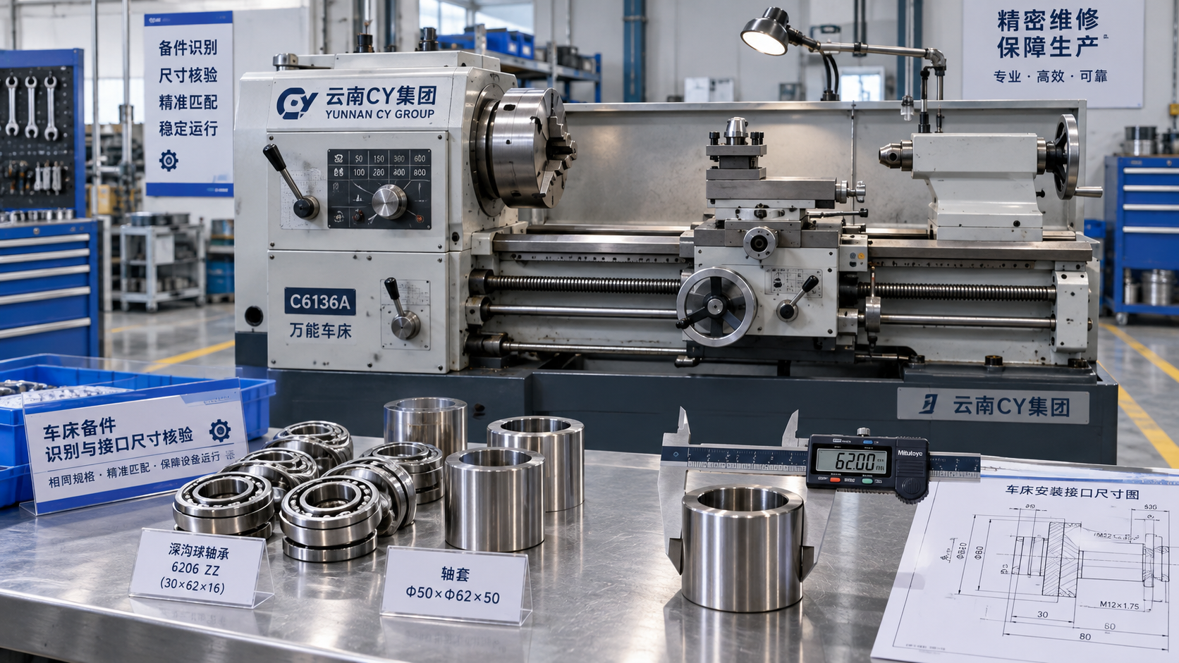
Ordering the wrong spare part for a Yunnan CY Group lathe can extend downtime, increase maintenance costs, and compromise machine performance after an apparently successful installation.
For after-sales maintenance technicians, compatibility requires more than a matching part number. Machine identity, installed configuration, mechanical interfaces, electrical specifications, and operating requirements must agree.
The most reliable approach combines machine-specific documentation, measurements from the installed component, and written supplier confirmation. Treat unresolved differences as reasons to pause the purchase.
This guide explains how to identify configuration differences, build a useful replacement specification, and verify the supplied component before returning your lathe to productive service.
What information should you collect before searching for a replacement?
Begin with the machine nameplate. Record the manufacturer name exactly as displayed, the complete model designation, serial number, and manufacturing date when available and clearly legible.
When searching for Yunnan CY Group parts, retain every model suffix. Similar model names do not establish compatibility across different configurations, production periods, or equipment options.
Photograph the complete machine, its nameplate, the component location, and surrounding connections. Include readable component labels and an overview showing how the assembly is installed.
Record the controller, drive, turret, chuck, and other relevant equipment manufacturers separately. A machine builder’s name alone cannot identify every purchased component fitted to a lathe.
Ask the customer about previous repairs and retrofits. An upgraded drive, replacement turret, or modified lubrication system may make original documentation insufficient for selecting parts.
Identify the failed component’s function and observed symptoms. Similar alarms or machining defects can result from wiring problems, contamination, incorrect settings, or another damaged component.
Before ordering, confirm the diagnosis through the applicable maintenance procedure. Replacing a healthy component wastes time and may leave the original fault unresolved after installation.
Which documents provide the strongest compatibility evidence?
Use the machine-specific parts list, assembly drawings, electrical diagrams, and maintenance manual together. Each document answers different questions about identification, interfaces, and installation requirements for replacement.
A parts list may identify an assembly without specifying every internal component. Establish whether the listed number refers to a complete unit or an individual spare.
Compare the document’s applicable model, revision, and serial-number range with the machine. A manual for a related lathe can provide context without proving interchangeability by itself.
Check the installed component label against the documented number, including prefixes, suffixes, and revision codes. Photograph unclear markings before cleaning methods potentially erase the remaining identification.
If numbers differ, investigate whether the component was replaced previously or the documentation is outdated. Do not assume a different number represents an approved successor part.
Ask the machine builder or supplier to explain any supersession in writing. Confirmation should identify the old number, replacement number, applicable machine, and required modifications explicitly.
Without reliable documentation, build a specification from measurements and component data. Recognize that measurement-based matching may leave material, tolerance, firmware, or performance requirements unresolved until confirmed.
How do you verify mechanical fit and operating capacity?
Measure the interfaces that determine installation: mounting-hole spacing, locating features, shaft diameter, bore size, overall envelope, and clearances. Record units and measurement methods alongside each result.
Use suitable measuring equipment for critical features. A ruler can establish approximate size, but bearing seats, locating diameters, and precision interfaces require more appropriate inspection methods.
Check shaft shoulders, keyways, splines, threads, and coupling geometry. Two components with identical external dimensions can transmit load differently or locate incorrectly inside the same assembly.
For bearings, confirm the full designation, accuracy requirements, internal clearance or preload arrangement, sealing, and lubrication conditions. Matching bore and outside diameter alone is insufficient evidence.
For belts and gears, compare profile, pitch, width, tooth count, and applicable load requirements. Verify the complete matched system when a proposed replacement changes transmission characteristics.
Ball screws require attention to lead, direction, nut arrangement, end machining, accuracy, and preload. A screw that physically fits can still alter positioning performance or repeatability.
For chuck components, verify the mounting interface, actuator connection, gripping arrangement, and rated limits. Compatibility directly affects workholding, making undocumented substitutions particularly difficult to justify safely.
Also compare speed, load, duty cycle, materials, and environmental requirements. Physical fit establishes only one part of compatibility; the replacement must perform under actual operating conditions.
What must match on electrical and control components?
Start with supply voltage, frequency where relevant, current requirements, and protective arrangements. Matching a connector or enclosure does not establish electrical compatibility with the machine circuit.
For motors, compare rated output, speed range, torque characteristics, mounting, shaft interface, feedback device, and brake requirements. Review the associated drive’s supported motor specifications as well.
A replacement servo motor must work with its drive and feedback system. Differences in encoder type, resolution, communication, or commutation requirements may prevent correct operation entirely.
Check connector pin assignments against wiring diagrams, including protective earth and shielding arrangements. Identical connector bodies may contain different signal assignments between component versions or manufacturers.
For proximity sensors, verify supply range, sensing distance, target requirements, output type, and normally open or closed behavior. Include PNP or NPN configuration where applicable too.
For drives and control modules, record exact model variants, hardware revisions, firmware, communication interfaces, and option cards. Confirm whether replacement requires parameter transfer, configuration, or commissioning.
Back up available parameters and relevant programs before removing functioning electronics, following approved procedures. A hardware-compatible replacement may still require machine-specific settings to restore correct behavior.
When replacing safety-related components, follow the applicable manufacturer procedure and validation requirements. Do not infer suitability from ordinary electrical ratings or bypass interlocks to demonstrate operation.
How should you check hydraulic and lubrication parts?
For pumps and valves, compare working pressure, flow, fluid compatibility, connection size, mounting, and control method. Verify continuous-duty requirements and the installed system’s actual operating conditions.
Thread identification deserves particular care. Similar-looking metric, BSP, and NPT connections are not interchangeable, and adapters can introduce clearance, sealing, or pressure-rating problems during installation work.
For solenoid-operated valves, check both the hydraulic function and coil specification. Voltage, power consumption, connector arrangement, and valve behavior must agree with the original circuit requirements.
For seals, establish material, dimensions, profile, and operating conditions. Fluid chemistry, temperature, pressure, and shaft motion determine suitability beyond the replacement’s appearance or nominal size alone.
Lubrication components must preserve the required delivery characteristics. An apparently suitable metering unit can supply an incorrect quantity, allowing wear to develop without immediate fault indications.
What should the supplier confirm before you place the order?
Send one consolidated identification package containing machine details, component numbers, photographs, measurements, and relevant drawing references. This reduces ambiguity and makes supplier answers easier to assess.
Request confirmation against your specific machine and installed configuration. A quotation stating only “suitable for Yunnan CY Group” provides insufficient evidence for a maintenance purchasing decision.
Clarify whether the offer is an original component, an approved replacement, or a proposed alternative. Those descriptions require different supporting evidence and should remain distinguishable throughout purchasing.
An alternative may be practical when original parts are unavailable, but require a comparison of critical specifications. Supplier confidence alone cannot resolve undocumented technical differences satisfactorily.
If a replacement requires modification, evaluate it as a controlled engineering change. Include implementation instructions, commissioning requirements, and effects on maintenance documentation in the approval process.
Agree on delivery time only after technical questions are resolved. Rapid shipment provides little benefit if the part arrives without necessary connectors, adapters, or commissioning information.
How can you decide whether the evidence is sufficient?
Use a short acceptance checklist covering identity, interfaces, operating ratings, control requirements, and installation conditions. Mark each item confirmed, conflicting, or unresolved before releasing the order.
A strong match combines a documented applicable part number with verified interfaces and ratings. Installation requirements should also be understood, including any manufacturer-directed adjustments or commissioning.
A dimensional match with incomplete electrical or performance data remains uncertain. Likewise, an apparently correct part number requires investigation when the installed component shows conflicting specifications.
Consider a replacement sensor that matches the thread and supply voltage but has a different output type. It may fit mechanically while providing an unsuitable signal.
Resolve that difference using the wiring diagram, input specifications, and confirmed sensor data. Avoid assuming the control system can accommodate a change without configuration or rewiring.
Keep the final comparison with the service record. Future technicians should see why the part was accepted, which documents supported the decision, and what changed afterward.
What should you verify when the replacement arrives?
Inspect the delivered component before dismantling the machine further. Check its label, revision, included accessories, visible condition, and packaging identification against the approved order and specifications.
Compare critical dimensions and interfaces with your recorded measurements. Raise discrepancies immediately, while the component remains uninstalled and the supplier can assess clear evidence of mismatch.
Prepare installation using the applicable maintenance instructions, isolation procedures, lifting arrangements, and cleanliness requirements. Hydraulic or pneumatic circuits may retain pressure after electrical power is disconnected.
Follow specified assembly settings and adjustment procedures. Bearing preload, coupling alignment, fastening torque, and seal installation can determine reliability even when the replacement itself is correct.
Commission progressively according to the machine and component instructions. Verify permitted basic functions before increasing speed, applying load, or returning the machine to normal production conditions.
Monitor relevant indicators such as alarms, temperature, vibration, leakage, axis movement, or lubrication delivery. Choose checks appropriate to the replaced component and the original failure mode.
Where repair affects machining performance, check positioning or produce a representative test component as appropriate. Successful power-up alone does not demonstrate restored accuracy or process capability.
Make compatibility a documented maintenance decision
For Yunnan CY Group lathes, reliable spare-part selection starts with the specific machine and its current configuration. Brand recognition and visual similarity cannot establish every requirement.
Combine documentary evidence, measured interfaces, operating specifications, and written supplier confirmation. Investigate conflicts before purchasing, then inspect and commission the delivered component using applicable maintenance procedures.
The practical decision is straightforward: order when critical requirements are confirmed, escalate unresolved differences, and record the final result so future repairs become faster and clearer.