• Global CNC market projected to reach $128B by 2028 • New EU trade regulations for precision tooling components • Aerospace deman
NYSE: CNC +1.2%LME: STEEL -0.4%

How to Specify a Multi-Axis Machining System for Tight-Tolerance Aerospace Parts
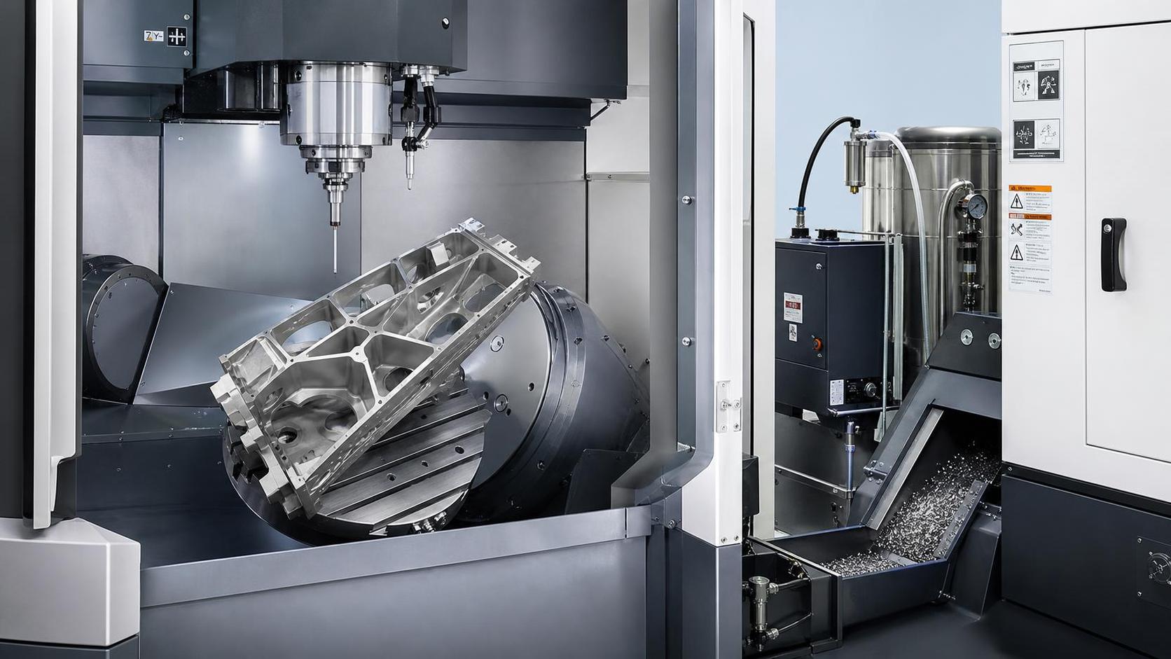
The real specification question: can the system hold the part, not just demonstrate a feature?
For aerospace work, a multi-axis machining system is rarely selected because a five-axis configuration looks more capable than a three-axis alternative. The purchase decision is usually tied to a more difficult question: can this machine repeatedly produce a defined family of parts within tolerance, across multiple shifts, materials, operators, and production lots, while maintaining an auditable quality record?
That distinction matters because aerospace parts often combine thin walls, deep pockets, compound angles, close positional tolerances, difficult materials, and relatively high consequences for process variation. A machine may successfully cut a demonstration impeller or structural bracket, yet still be unsuitable for production if thermal drift, fixturing access, probing reliability, chip evacuation, or tool-change consistency introduces uncontrolled variation.
Technical evaluators should therefore treat a Multi-axis Machining System for Aerospace as a production capability decision rather than an axis-count decision. The machine tool is one part of a system that also includes CAM strategy, workholding, cutting tools, probing, coolant management, inspection, automation, and process data. Weakness in any of those areas can determine whether the theoretical machine accuracy becomes actual part accuracy.
Start with the part family and the quality risk
The most useful first step is to classify the intended parts by manufacturing risk, not by broad labels such as “aerospace component.” A titanium structural fitting, an aluminum monolithic frame section, an Inconel engine component, and a precision actuator housing may all require multi-axis machining, but they stress the manufacturing system in different ways.
For example, aluminum aerospace structures may require aggressive material removal with strict control of wall deformation. Nickel-based superalloys generally place greater demands on rigidity, spindle torque, thermal control, coolant delivery, and tool-life management. Precision housings may be less challenging from a cutting-force perspective but more sensitive to bore geometry, feature-to-feature position, and repeatable datum transfer.
The evaluation file should identify the dimensions that truly govern acceptance. These may include:
- Profile tolerances on aerodynamic or contoured surfaces.
- True-position requirements between holes, bores, and machined datum features.
- Flatness, perpendicularity, and parallelism after material removal and clamping release.
- Surface-integrity requirements in fatigue-critical or sealing areas.
- Wall thickness limits and the risk of deflection during machining.
- Traceability requirements for tooling, probing, inspection, programs, and process changes.
A common mistake is to specify the machine according to the tightest nominal tolerance on the drawing alone. A 10-micron dimensional requirement does not automatically mean that every machine subsystem must be rated at 10 microns. What matters is the complete error budget: machine geometry, thermal movement, probe uncertainty, fixture repeatability, tool deflection, tool wear, part distortion, measurement uncertainty, and environmental conditions all consume part of the allowable variation.
If that budget has not been discussed, a machine comparison based on brochure positioning accuracy can create false confidence.
Axis configuration matters, but kinematics matter more
“Five-axis” covers several fundamentally different machine architectures. A trunnion-style configuration, a swivel-head machine, a gantry system, and a machine with a rotary table can all provide five-axis interpolation, yet their behavior under load, accessibility, envelope, and thermal conditions can differ significantly.
For smaller prismatic components and complex housings, a compact trunnion machine can provide short tool paths and strong access to multiple faces. However, its work envelope may be constrained by the fixture, rotary-table diameter, and collision clearance. For larger structural parts, a moving-column or gantry-style platform may offer the necessary reach, but long travel axes introduce additional questions about stiffness, positioning behavior, and thermal response across the machining envelope.
Swivel-head configurations can be attractive where workpieces are heavy or awkward to rotate. Keeping the component stationary may improve fixture design and reduce rotary-axis inertia. Yet the head geometry, spindle length, and angular range must still be evaluated against access to deep features and potential interference with clamps, probes, and toolholders.
Technical teams should request machine-specific information on the following rather than relying on generic “simultaneous five-axis” capability:
- Rotary-axis range, speed, acceleration, backlash compensation, and clamping behavior.
- Dynamic stiffness in common tool orientations, especially at extended reach.
- Tool center point control and rotary-axis calibration methods.
- Actual usable envelope after accounting for fixtures, part rotation, tool length, and collision zones.
- Interpolation behavior during contouring, including the control’s look-ahead and smoothing functions.
- Accessibility for setup, probing, manual inspection, chip removal, and maintenance.
More axes do not necessarily reduce cycle time. In some parts, a 3+2 strategy with rigid positioning may deliver better stability and simpler verification than continuous five-axis motion. Simultaneous machining becomes more valuable when it improves tool orientation, maintains a favorable cutting condition on complex surfaces, eliminates multiple setups, or enables access that fixed-axis machining cannot provide.
The correct question is not “Do we need five-axis machining?” It is “Which operations genuinely benefit from continuous motion, and which should remain indexed for process stability?”
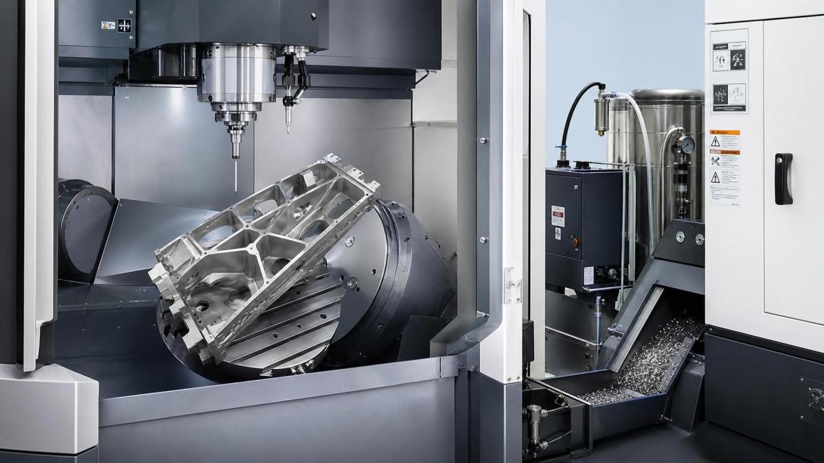
Accuracy must be evaluated as a thermal and process capability issue
Machine accuracy specifications are often read as permanent properties. In practice, aerospace machining exposes the gap between static acceptance-test results and operational performance. A machine can show strong geometric accuracy in a controlled test condition while drifting during a long titanium roughing cycle, changing behavior as the spindle warms, or responding differently after rotary-axis movement and coolant exposure.
Thermal stability should be a central evaluation criterion for tight-tolerance work. This includes spindle cooling, ball-screw and drive thermal management, machine structure design, coolant temperature control, and the machine’s ability to compensate for predictable thermal changes. The supplier should be able to explain what temperature sensors and compensation models are included, what conditions they address, and how they are maintained or recalibrated.
Evaluators should be cautious with a familiar but incomplete claim: “The machine has thermal compensation, so drift is no longer a concern.” Compensation can reduce predictable movement. It cannot fully remove the effects of changing ambient conditions, unusual cutting loads, poor coolant control, an unstable foundation, or inconsistent warm-up practices.
A more useful acceptance approach is to define representative machining trials. These trials should include material close to production grade, meaningful cutting time, realistic tool extension, intended workholding, in-process probing where applicable, and measurement after the machine has reached normal operating conditions. A short air-cut demonstration is not evidence of production capability.
Spindle selection should follow material removal behavior
Spindle speed receives attention because it is easy to compare. For aerospace machining, torque, power curve, bearing design, taper interface, thermal behavior, and toolholder compatibility can be equally important.
High-speed spindles can be effective for aluminum structural machining, especially when paired with suitable high-performance cutters and reliable chip evacuation. But a spindle optimized for very high rotational speed may not be the best choice for deep cuts in titanium or Inconel, where low- to mid-range torque, rigidity, and heat management often dominate the decision.
Technical evaluators should review spindle performance at the actual intended cutting range, not only maximum values. Ask for torque and power curves, continuous versus peak ratings, allowable duty cycle, recommended toolholder interfaces, and expected maintenance requirements. The interface itself matters: the selected taper or polygonal connection should support the intended cutting loads, tool-change frequency, and runout expectations.
Runout should not be treated only as a spindle specification. The production result depends on the stack-up of spindle interface, holder, collet or hydraulic chuck, tool assembly, balance condition, and tool projection. On tight-tolerance bores or high-value finishing operations, the tooling standard and assembly controls may deserve the same level of attention as the machine purchase.
Workholding and probing are part of the machine specification
A multi-axis machine cannot compensate for an unstable datum strategy. Aerospace parts frequently require fixtures that balance access, rigidity, low distortion, repeatable loading, and the ability to manage multiple machining states. A fixture that works in a single setup may become unsuitable once chip loads, part relaxation, or automated loading are introduced.
Machine selection should therefore proceed with an early workholding concept. Consider the mass and center of gravity of the fixture-plus-part assembly, rotary-axis loading limits, clamp access during tilted tool orientations, and the number of setup changes required to complete the component. Check whether hydraulic, pneumatic, vacuum, zero-point, or modular fixturing systems are appropriate for the material and geometry.
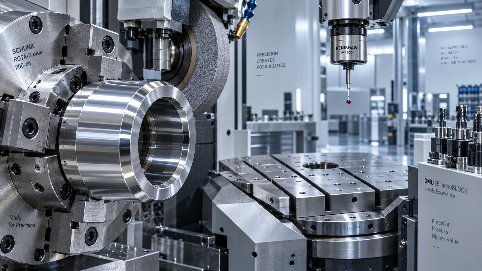
Probe capability is also frequently oversimplified. A spindle probe can support work offset setting, part location, feature checks, and certain forms of adaptive process control. It does not replace a measurement strategy. Probe qualification routines, stylus selection, accessibility, coolant contamination, collision protection, and data retention all influence reliability.
For higher-risk programs, define which checks must occur in the machine, which must occur on a coordinate measuring machine, and which characteristics require special gauges or non-contact inspection. The system should be designed so that in-process data and final inspection results can be connected to the same part serial number or manufacturing record where required by the customer’s quality system.
Automation should be justified by stability, not labor reduction alone
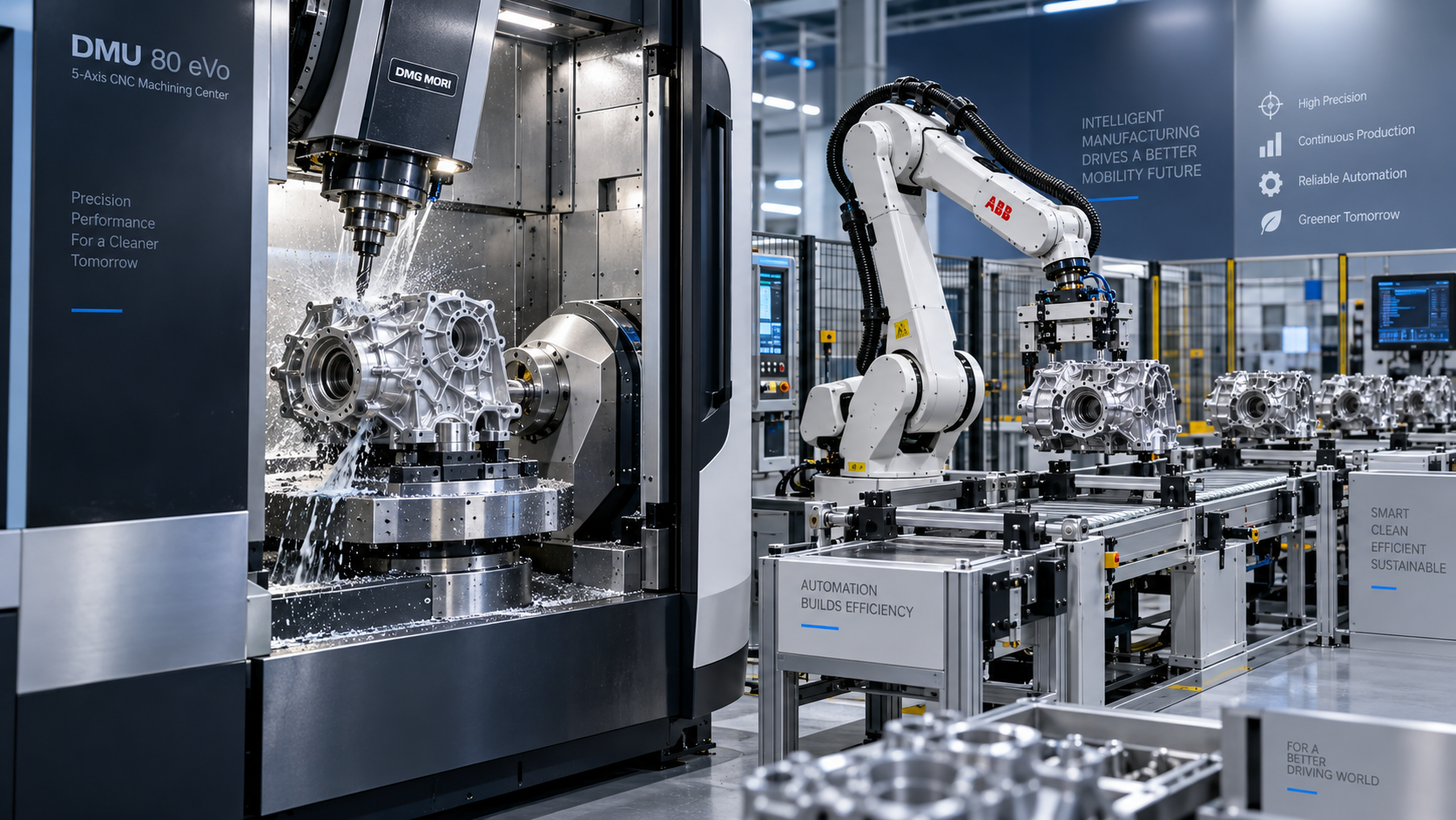
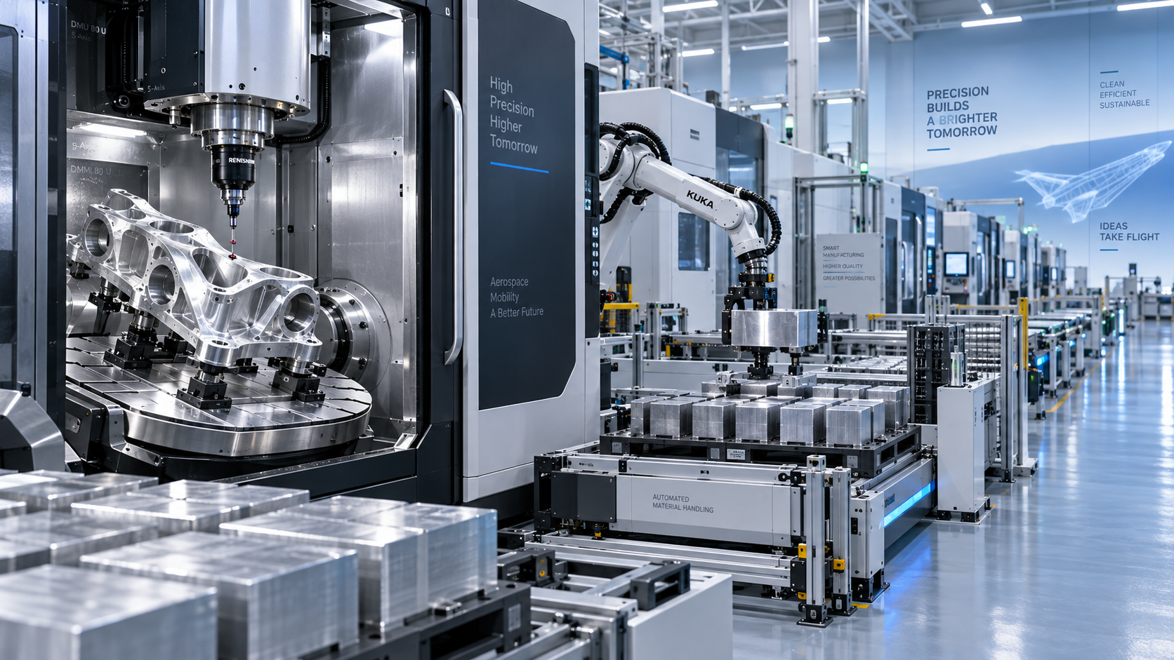
Automation is increasingly relevant in aerospace supply chains, particularly where machine utilization, skilled labor availability, and unattended operation are concerns. Pallet pools, robot loading, automated tool management, and integrated material handling can improve throughput. But their value depends on process maturity.
Automating an unstable machining process usually makes the instability more expensive. Before committing to a pallet system or robot cell, assess tool-life predictability, chip control, fixture consistency, probe reliability, recovery procedures, and the ability to isolate a nonconforming part without disrupting the entire flow.
A practical automation review should include the recovery case: what happens after a broken tool, probe alarm, interrupted cycle, tool-life limit, pallet misload, or power loss? If operators cannot safely and consistently restore the system to a known state, the automation design may not be ready for unattended production.
Digital connectivity has a similar limitation. Machine monitoring, tool-condition data, program revision controls, and production dashboards are useful only when the data supports decisions. Technical teams should prioritize traceability of program versions, tool offsets, alarm history, inspection results, and maintenance events over collecting large volumes of machine data with no defined ownership or response process.
Supplier evaluation should extend beyond the machine delivery date
Aerospace programs can remain active for years, sometimes with uneven volumes and changing revision requirements. This makes service capability, spare-parts availability, control-system support, calibration access, and applications engineering relevant procurement factors.
For an international supply decision, confirm where the supplier’s service engineers are located, what response commitments are contractually available, which components are locally stocked, and whether the chosen control platform can be supported over the expected program life. It is also reasonable to clarify responsibility for installation, foundation requirements, geometric acceptance, operator training, postprocessor development, and production prove-out.
Price comparisons should include these lifecycle requirements. A lower acquisition price may be offset by limited service coverage, expensive proprietary consumables, unavailable application support, or long recovery times after a spindle or control issue. Conversely, a highly specified machine may be difficult to justify if the projected part mix does not use its thermal, automation, or simultaneous-machining capability.
Turn the purchase decision into a measurable acceptance plan
The strongest specification documents do not end with a list of axis travels and spindle ratings. They define the evidence required before final acceptance. That can include machine geometry tests, thermal run data, representative cutting trials, surface-finish verification, probing repeatability checks, cycle-time targets, capability-study expectations, and documentation deliverables.
Not every requirement needs to be imposed at the same level. A prototype shop may accept greater setup involvement in exchange for flexibility. A repeat-production aerospace supplier may place more weight on pallet repeatability, tool monitoring, traceable offsets, and predictable recovery. The evaluation criteria should reflect the commercial model as well as the drawing tolerance.
Ultimately, the right multi-axis system is the one that creates a controlled and supportable process for the actual part family. Axis count, spindle speed, automation level, and control features all matter, but they matter only when they reduce a defined production risk. For aerospace evaluators, that is the basis for a defensible selection: not the most impressive machine specification, but the most credible route to repeatable conforming parts.
Recommended for You
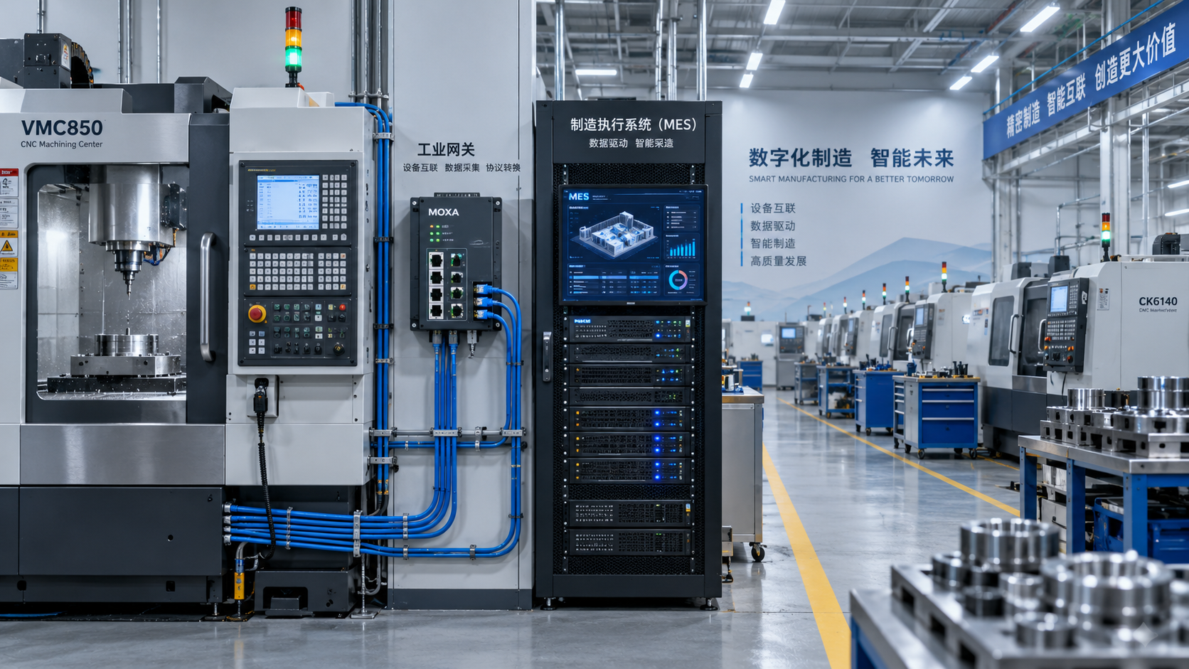
 Digital Manufacturing for Smart Factories: Connecting Legacy Machines to MESMachine Tool Industry Editorial Team
 How to Select a CNC Metal Lathe for Tight-Tolerance Shaft and Sleeve PartsCNC Machining Technology Center
 How to Select an Industrial Lathe for High-Volume Shaft ProductionMachine Tool Industry Editorial Team
 Selecting Machine Tools for Automotive Parts: Accuracy, Throughput, and AutomationMachine Tool Industry Editorial Team
 Industrial Machining: Selecting Processes for Tight-Tolerance Metal PartsCNC Machining Technology Center
 Manufacturing Technology Trends That Improve Throughput and Quality ControlManufacturing Market Research Center

Aris Katos
Future of Carbide Coatings
15+ years in precision manufacturing systems. Specialized in high-speed milling and aerospace grade alloy processing.
▶
Is Learning CNC Programming Worth It for Shop Owners Seeking Higher Margins?CNC Machining Technology Center▶
How to Select CNC Equipment for High-Mix, Low-Volume ProductionCNC Machining Technology Center▶
Can CNC Machining Inconel Control Tool Wear in High-Temperature Aerospace Parts?CNC Machining Technology Center▶
How Automated Precision Machining Maintains Tolerance in High-Mix ProductionCNC Machining Technology Center▶
CNC Programming Explained: From CAD Models to Reliable Shop-Floor ToolpathsCNC Machining Technology Center
Mastering 5-Axis Workholding Strategies
Join our technical panel on Nov 15th to learn about reducing vibrations in thin-wall components.

Providing you with integrated sanding solutions
Before-sales and after-sales services
Comprehensive technical support